3-way switch wiring diagrams are essential for understanding how to control lights from multiple locations. They provide a clear guide for safe and correct installation‚ ensuring reliable performance and troubleshooting common issues effectively.
What is a 3-Way Switch?
A 3-way switch is an electrical device used to control a light fixture from two different locations. It has three terminals: a common terminal and two traveler terminals. Unlike a standard single-pole switch‚ a 3-way switch does not have an “on” or “off” position. Instead‚ it works in conjunction with another 3-way switch to create a circuit that allows power to flow through the traveler wires. This setup enables seamless control of a single light fixture from multiple points‚ making it ideal for hallways‚ staircases‚ or large rooms. The switch operates by directing the electrical current through different paths‚ ensuring the light can be turned on or off from either location.
Importance of Wiring Diagrams for 3-Way Switches
Wiring diagrams are crucial for installing and troubleshooting 3-way switches. They provide a clear visual representation of how wires should be connected‚ ensuring safety and proper functionality. Without a diagram‚ identifying the common‚ traveler‚ and ground wires can be confusing‚ leading to potential electrical hazards. Diagrams also help in planning the circuit layout‚ especially when controlling lights from multiple locations. They simplify the process of connecting wires between switches and light fixtures‚ reducing the risk of short circuits or open circuits. By following a wiring diagram‚ individuals can ensure compliance with electrical standards and achieve reliable performance. This visual guide is essential for both professionals and DIYers to avoid mistakes and complete the job efficiently.
Common Applications of 3-Way Switches
3-way switches are widely used in various lighting setups to control fixtures from multiple locations. They are ideal for staircases‚ hallways‚ and large rooms where lights need to be operated from different points. These switches are also commonly installed in homes for controlling ceiling fans or dimmer systems. In commercial settings‚ they are used to manage lighting in conference rooms or corridors. Additionally‚ 3-way switches are integral in smart home systems‚ enabling seamless integration with automation technologies. Their versatility allows them to be paired with dimmers or used in complex lighting configurations. This makes them a practical solution for enhancing convenience and energy efficiency in both residential and commercial spaces.

Understanding the Components of a 3-Way Switch
A 3-way switch features a unique structure with three terminals: common‚ traveler‚ and ground wires. These components enable control of a light fixture from two locations.
Structure and Terminals of a 3-Way Switch
A 3-way switch has a distinct structure designed for controlling lights from multiple locations. It features three terminals: the common terminal and two traveler terminals. The common terminal connects to the power source or light fixture‚ while the traveler terminals connect to the other switch in the circuit‚ enabling the flow of electricity between locations. Additionally‚ a grounding terminal is present for safety‚ ensuring electrical currents are properly grounded. Understanding the function of each terminal is crucial for accurate wiring. Properly connecting these terminals allows seamless operation of the switch‚ whether controlling a single light or multiple fixtures in a complex setup. This setup ensures reliable performance and safe electrical connections.
Types of Wires Used in 3-Way Switch Wiring
In 3-way switch wiring‚ specific types of wires are used to ensure proper electrical connections. The hot (black) wire carries power from the circuit breaker to the switch or light fixture. The red and white wires act as traveler wires‚ connecting the two 3-way switches and allowing the current to flow between them. The neutral (white) wire completes the circuit‚ while the bare copper wire serves as the ground‚ providing safety by directing stray currents away from the system. Additionally‚ 12-gauge or 14-gauge wires are commonly used‚ depending on the circuit’s amperage requirements. Proper identification and use of these wires are critical for safe and functional installation‚ ensuring the switches control the lights effectively without electrical hazards.
Role of the Neutral and Ground Wires
In 3-way switch wiring‚ the neutral and ground wires play crucial roles in ensuring safe and proper electrical connections. The neutral wire (typically white) completes the circuit by returning current to the power source‚ while the ground wire (bare copper) provides a safety path for stray currents‚ protecting against electrical shocks. The neutral wire is essential for the operation of the light fixture‚ as it allows the circuit to function correctly. The ground wire‚ on the other hand‚ is not part of the main circuit but serves as a protective measure‚ ensuring user safety. Both wires must be correctly connected to avoid hazards and ensure reliable operation of the 3-way switch system.

Different Types of 3-Way Switch Wiring Diagrams
3-way switch wiring diagrams include basic setups‚ dimmer configurations‚ and multi-light systems. Each diagram illustrates specific connections for controlling lights from multiple switches‚ ensuring clarity and safety.
Basic 3-Way Switch Wiring Diagram
A basic 3-way switch wiring diagram shows two switches controlling one light fixture. The setup involves a common wire and two traveler wires. The common wire connects to the light‚ while the travelers link the switches. This configuration allows seamless control from either switch‚ ensuring the light operates consistently. Proper wiring is crucial to avoid short circuits or open connections. Using a wiring diagram ensures safety and correct installation‚ making it easier to understand and troubleshoot the circuit. This setup is ideal for hallways or staircases where dual control is necessary. Always follow local electrical codes and use appropriate tools for a safe and reliable connection.
3-Way Switch with Dimmer Wiring Diagram
A 3-way switch with dimmer wiring diagram illustrates how to integrate a dimmer into a multi-location lighting control system. This setup allows adjusting light levels from two locations‚ combining the functionality of a 3-way switch with a dimmer. The dimmer is typically installed at one location‚ replacing a standard switch‚ while the other remains a 3-way switch. The wiring involves connecting the dimmer to the common wire and the traveler wires linking both switches. Neutral and ground wires must also be properly connected for safe operation. This configuration requires compatible dimmers designed for 3-way systems‚ such as LED or smart dimmers. Always follow the manufacturer’s instructions and local electrical codes to ensure a safe and functional installation. This setup enhances lighting control and energy efficiency while maintaining the convenience of multi-location switching.
3-Way Switch Wiring Diagram with Multiple Lights
A 3-way switch wiring diagram with multiple lights explains how to control several fixtures from two locations. This configuration involves connecting the common wire to the light fixtures and using traveler wires to link the switches. Each light is wired in parallel‚ ensuring all fixtures operate simultaneously. The neutral wire is connected to the light fixtures‚ while the ground wire ensures safety. Properly connecting the traveler wires between switches is crucial for synchronized control. This setup is ideal for large rooms or hallways where multiple lights need to be controlled from different points. Always follow safety guidelines and local electrical codes to avoid hazards. This diagram simplifies the installation process‚ ensuring reliable and efficient control of multiple lights from two locations.

Step-by-Step Installation Guide
Start by gathering tools and materials‚ then turn off the power. Follow the wiring plan to connect wires to switches and fixtures‚ ensuring safe and correct installation.
Preparing the Necessary Tools and Materials
To successfully install a 3-way switch‚ gather essential tools and materials. Start with a screwdriver set‚ wire strippers‚ and pliers for handling wires; Use a voltage tester to ensure power is off before starting. For materials‚ you’ll need 14/3 or 12/3 gauge wire for connections between switches and lights. Include a 3-way switch‚ light fixtures‚ and compatible wall plates. Ensure all components match your wiring diagram. Safety gear like gloves and safety glasses is crucial. Lastly‚ refer to your wiring diagram to verify the required tools and materials‚ ensuring compliance with local electrical codes for a safe and efficient installation process.
Understanding the Wiring Plan
Before starting your 3-way switch installation‚ thoroughly understand the wiring plan. Identify the power source‚ traveler wires‚ and load connections. The wiring diagram will illustrate how power flows from the electrical panel to the switches and finally to the light fixture. Locate the common terminals on each switch‚ which are typically marked with a “COM” label or a different color. Traveler wires connect the switches‚ enabling communication between them. Ensure the neutral and ground wires are correctly connected for safety. Trace the diagram step-by-step to confirm all connections‚ starting from the power source and ending at the light. This understanding is crucial for a safe and functional installation‚ preventing errors and ensuring proper operation of your lighting system.
Connecting the Wires to the Switch and Light Fixture
Connecting the wires to the switch and light fixture requires careful attention to the wiring diagram. First‚ identify the hot‚ neutral‚ and ground wires. Attach the hot wire to the common terminal on the first 3-way switch. Next‚ connect the traveler wires between the two switches‚ ensuring they are securely fastened to the traveler terminals. The common terminal on the second switch should then be connected to the hot wire leading to the light fixture. The neutral wire is connected directly to the fixture‚ bypassing the switches. Finally‚ connect the ground wire to both switches and the fixture to ensure a safe grounding path. Always turn off the power to the circuit before starting and use a voltage tester to confirm there is no power present. Double-check all connections against the diagram to ensure everything is correctly wired. If the light does not function properly‚ re-examine the connections for any potential errors. Consider consulting additional resources or tutorials for visual guidance to help with the process. By following these steps meticulously‚ you can successfully wire your 3-way switch setup‚ ensuring both functionality and safety.
Troubleshooting Common Issues
Common issues include short circuits‚ flickering lights‚ and open circuits. Use wiring diagrams to identify and resolve faults efficiently‚ ensuring safe and proper electrical connections.
Identifying and Fixing Short Circuits
A short circuit in a 3-way switch setup occurs when wires unintentionally connect‚ causing excessive current flow. To identify‚ turn off power and use a voltage tester to check for live wires. If a short is detected‚ locate the faulty connection by inspecting wires for damage or improper connections. Common causes include loose terminals or wires touching improperly. To fix‚ turn off power‚ then carefully examine the wiring diagram to trace connections. Use needle-nose pliers to separate wires and ensure all terminals are secure. Replace any damaged wires and verify the circuit with a multimeter before restoring power. Always follow safety guidelines to avoid electrical shocks or further damage.
Resolving Issues with Light Flickering
Light flickering in a 3-way switch setup often indicates loose connections or improper wiring. Start by turning off the power and inspecting the wires for secure connections at both the switch and the light fixture. Verify that travelers and common wires are correctly hooked up according to the wiring diagram. If flickering persists‚ check for damaged or faulty wires and replace them if necessary. Ensure the switch is functioning properly and consider replacing it if it shows signs of wear. Additionally‚ flickering could be caused by dimmer compatibility issues; ensure the dimmer is compatible with the light fixture. Consult the wiring diagram to confirm connections and test the circuit with a multimeter for voltage consistency. Always follow safety guidelines when troubleshooting electrical systems.
Diagnosing and Repairing Open Circuits
Diagnosing open circuits in a 3-way switch system involves identifying breaks in the wiring that prevent electricity from flowing. Start by turning off the power and using a multimeter to test for continuity across the circuit. Check all connections at the switches and light fixtures‚ ensuring wires are securely attached. Inspect the wiring for damage‚ such as cuts or burns‚ and repair or replace faulty sections. Verify that traveler and common wires are correctly connected according to the wiring diagram. If an open circuit persists‚ trace the wiring to locate the break and reconnect or replace the affected wire. Always ensure the circuit is de-energized before performing repairs to avoid electrical shock or further damage.
Safety Precautions and Best Practices
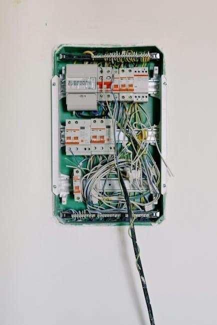
Always turn off power at the circuit breaker before starting work. Use a multimeter to verify de-energization. Wear protective gear‚ including gloves and safety glasses. Ensure all connections are secure and meet local electrical codes. Avoid overloaded circuits and use appropriate tools for the task to prevent accidents and ensure reliable results.
Ensuring Safe Electrical Connections
To ensure safe electrical connections when working with 3-way switches‚ always turn off the power at the circuit breaker and verify de-energization using a multimeter. Wear protective gear‚ including gloves and safety glasses‚ to prevent accidents. Use tools with insulated handles to avoid shock. Follow the wiring diagram carefully‚ ensuring all connections are tight and secure. Avoid overloading circuits‚ as this can lead to short circuits or fires. Double-check that all wires are properly stripped and connected to the correct terminals. Never leave loose wires or exposed conductors‚ as they pose a significant safety hazard. Always adhere to local electrical codes and regulations to guarantee compliance and safety.
Using Proper Tools and Protective Gear
Using proper tools and protective gear is crucial when working with 3-way switch wiring diagrams to ensure safety and efficiency. Essential tools include needle-nose pliers‚ wire strippers‚ screwdrivers‚ and a multimeter for troubleshooting. Protective gear such as insulated gloves‚ safety glasses‚ and a non-contact voltage tester prevents electrical shocks and injuries. Always use tools with insulated handles to avoid direct contact with live wires. Ensure all tools are in good condition to prevent accidental shorts or slips. Wearing protective gear minimizes risks‚ especially in complex installations. By adhering to these guidelines‚ you can safely navigate the wiring process and avoid potential hazards associated with electrical work.
Following Local Electrical Codes and Regulations
Adhering to local electrical codes and regulations is vital when installing 3-way switches to ensure compliance and safety. These codes dictate wiring practices‚ materials‚ and installation methods. Always consult your area’s specific guidelines to avoid legal issues or hazards. Proper permitting and inspections may be required‚ especially for new installations. Familiarize yourself with requirements for wire gauges‚ connections‚ and grounding. Non-compliance can lead to fines or system failures. Following these regulations helps maintain a safe and reliable electrical system‚ protecting both property and occupants from potential risks. Stay informed and up-to-date with any changes in local codes to ensure all installations meet current standards and best practices.

Resources and Downloads
Download free PDF guides for 3-way switch wiring diagrams‚ offering detailed instructions and visual aids. Access tutorials and tools for seamless installation and troubleshooting.
Free PDF Downloads for 3-Way Switch Wiring Diagrams
Access comprehensive free PDF guides for 3-way switch wiring diagrams. These resources provide detailed step-by-step instructions‚ visual diagrams‚ and troubleshooting tips. Perfect for DIY enthusiasts and electricians‚ they cover various configurations‚ including dimmer setups and multiple light controls. Download these PDFs to ensure safe and efficient installations. They also include safety precautions and best practices‚ making them invaluable for both beginners and professionals. These guides are regularly updated to reflect the latest electrical standards and technologies‚ ensuring you have the most accurate information at your fingertips. Visit trusted sources to download these essential resources today and simplify your wiring projects.
Recommended Tools for 3-Way Switch Installation
Installing a 3-way switch requires the right tools to ensure safety and efficiency. Essential tools include a voltage tester to verify power absence‚ wire strippers for precise wire preparation‚ and screwdrivers (both flathead and Phillips) for switch and fixture connections. Needle-nose pliers are useful for bending and reaching wires‚ while a drill and fish tape aid in running wires through walls. A multimeter can help diagnose circuit issues‚ and a ladder or step stool provides safe access to higher areas. Don’t forget safety gloves and protective eyewear. These tools ensure a professional and secure installation‚ making the process easier and reducing the risk of errors or injuries.
Online Tutorials and Video Guides
Online tutorials and video guides are invaluable resources for mastering 3-way switch wiring. Platforms like YouTube and DIY forums offer step-by-step instructions‚ while websites like cbyge.com provide detailed PDF guides. These resources often include visual diagrams‚ making complex wiring processes easier to understand. Video tutorials are particularly helpful‚ as they demonstrate real-time installations and troubleshooting techniques. Many guides also cover advanced topics‚ such as integrating smart home technology or combining 3-way and 4-way switches. These resources are perfect for both beginners and experienced electricians‚ ensuring safe and efficient installations. By following these guides‚ you can confidently tackle even the most complex wiring projects with precision and accuracy.
Advanced Applications of 3-Way Switches
Advanced applications of 3-way switches include smart home integration‚ complex lighting systems‚ and combining with 4-way switches for enhanced control and functionality.
Integrating Smart Home Technology
Integrating smart home technology with 3-way switches enhances lighting control and automation. Smart switches can replace traditional 3-way switches‚ enabling voice or smartphone app control. These devices often require a neutral wire connection‚ which may need to be verified in older systems. Compatibility with hubs like SmartThings or Alexa ensures seamless integration. Dimmer capabilities can be added for adjustable lighting. Installation involves replacing existing switches and configuring them within your smart home network. This setup allows remote access and scheduling‚ improving convenience and energy efficiency. Ensure compatibility with your system and wiring before installation to avoid issues. Proper setup enables advanced features like scene control and energy monitoring‚ making your lighting system modern and efficient.
Using 3-Way Switches in Complex Lighting Systems
3-way switches are versatile components in complex lighting systems‚ enabling control from multiple locations. They are ideal for large spaces like staircases or hallways. By incorporating traveler wires‚ these switches allow for seamless communication between different control points. In multi-light setups‚ 3-way switches can manage several fixtures simultaneously. They are also compatible with dimmers and smart technology for enhanced functionality. Proper wiring is crucial to ensure reliable operation. Diagrams often show power entering the first switch‚ traveling through the system‚ and terminating at the last switch. This configuration ensures all lights respond correctly to each control point. Using 3-way switches in complex systems offers flexibility and efficiency‚ making them a preferred choice for modern lighting designs. Always refer to detailed wiring diagrams to avoid installation errors and ensure optimal performance.
Combining 3-Way and 4-Way Switches
Combining 3-way and 4-way switches allows for advanced lighting control in larger systems. A 4-way switch is typically installed between two 3-way switches‚ enabling control from three or more locations. The 3-way switches act as the starting and ending points of the circuit‚ while the 4-way switches provide intermediate control. Proper wiring is essential‚ with traveler wires connecting the switches. The common terminal on the 3-way switches links to the power source or light fixture. This setup is ideal for complex lighting systems‚ offering enhanced flexibility and control. Diagrams often illustrate this configuration‚ ensuring correct connections for reliable operation. By integrating 3-way and 4-way switches‚ you can achieve multi-point control in even the most intricate lighting designs.

